Presonus Eris 3.5 Repair | Crackling / Popping / Hissing noises!

My barely 3-year-old Presonus Eris 3.5 monitors have started making crackling, popping, and hissing noises—depending on their mood!

Two capacitors have gone bad, and the local distributor asked for $200 for the repair, whereas a new pair nowadays costs only $100.

The distributor in a neighbouring country mentioned that there’s no service available for these monitors, claiming they are ‘commercially developed in a production line,’ although the meaning behind that statement is a bit unclear to me.

It seems they might be suggesting that these monitors are mass-produced and not designed for individual repair or servicing. I don’t see how that can be the case, but let’s move along, like obedient citizens in a world of placebo abundance 😀

If you’re facing a similar problem and have access to a soldering iron (or know someone who does :P), consider replacing the two brown capacitors with 24v 1000μF ones, or any other bulging in the cap ones that seem suspect. Good new parts are available everywhere nowadays and cost less than 50cents each…

The problematic capacitors in my case were the bulging brown ones marked with the purple arrows in the following image.

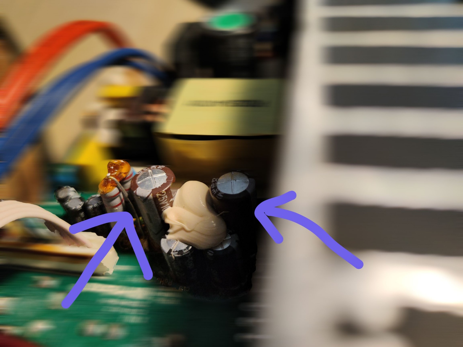
Needless to say, if you decide to tackle the project, do so at your own risk. The circuit involves a high current mains side, so take all necessary precautions to protect yourself.

Have a good one!

DIY Motorized Focuser for FSQ 106ED Telescope

The goal of this project was for the automated focusing system to have great holding torque (80Ncm) for heavy image trains (4-5kg) and very fine steps to accommodate the super tight FSQ106 critical focus zone.

The formula to calculate the critical focus zone on a telescope is :
CFZ = Focal Ratio * Focal Ratio * 2.2
For the FSQ106ED we have : CFZ = 5 * 5 * 2.2 = 55microns
So to be able to have perfect focus achieved we need every step on the motor to be 55microns or less for even better resolution.

The motor used on this build is geared and has a reduction of 250:3 which gives us 4000 steps per revolution.

One full revolution on the focuser coarse knob (where we are coupling our motor) makes the focuser move 29.8mm.
Now we have all the data we can do the maths 😛
(29.8mm * 1000) / 4000 = 7.45 microns per step.

The actual resolution achieved with this build is 7.45 microns per motor step!

Lathe – Threading gear calculator

Having bought a lathe for various DIY projects back in 2015, i quickly discovered the need to cut some unusual thread pitches (Astronomy adapters in particular have some of the weirdest out there).

The lathe manual (or the housing of the transmission system :D) , usually provides some information regarding the gearing for the most used ones, such as 0.05mm, 0.1mm, 0.2mm, 0.4mm, 0.5mm, 1mm and so forth.

But nothing for lets say an M42x0.75 adapter widely used in photography and astronomy!

While looking through the web in 2016 for a lathe gear calculator there was none to be found, that took into consideration the spindle to gear A ratio.
The spindle in this specific lathe (and many other brands from what i have read ) has a ratio of 4.5 turns. So in order for gear A to make a full turn the spindle makes 4.5 turns.

Without this number the usual quadrant calculations for gearing lathes, obviously fails and your thread pitches are not what you have expected at all 😛

Here is a very crude calculator for finding out possible, combinations of gears in a metric lathe (that is, a lathe with a metric leadscrew although it can cut some imperial threads by approximation), in order to produce the desired pitch when cutting threads!

Do note that some of the produced combinations, are not feasible at all for the time being, but I will upgrade it when time permits.

Lathe threading gear calculator

Have fun!